MIB 3D Volume Rendering
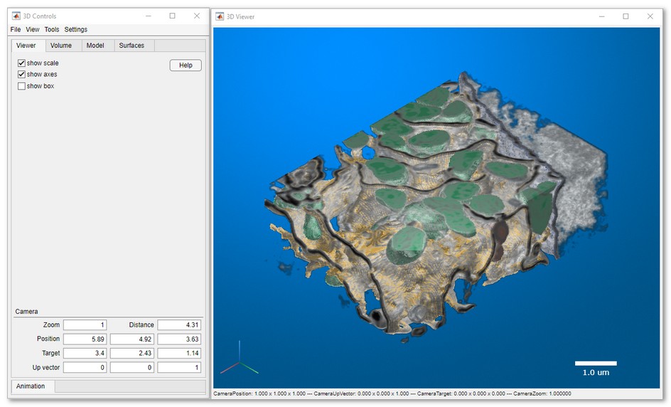
Starting from MIB version 2.84 a new 3D volume rendering engine is available. This engine requires MATLAB R2022b or newer and at least for R2022b available on in MIB for MATLAB.
A brief demonstration is available in the following video:
Introduction to an updated 3D viewer:  https://youtu.be/840o6zni3KE
Back to Index --> User Guide --> Menu --> File
collapse all on page
Contents
-
How to enable the new 3D viewer for MATLAB R2022b or newer
-
Downsampling of datasets
-
Composition of the 3D viewer
-
3D Controls -> Menu
-
3D Controls -> Viewer
-
3D Controls -> Volume
-
3D Controls -> Model
-
3D Controls -> Surfaces
-
3D Controls -> Animation
collapse all
How to enable the new 3D viewer for MATLAB R2022b or newer
Expand this section to see details
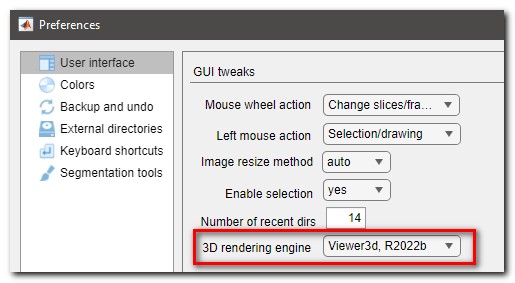
Use MIB Preferences dialog ( MIB->Menu->File->Preferences->User interface->3D rendering engine) to select default rendering engine.
-
Viewer3d, R2022b, selects the new version of the viewer described on this page
-
Volshow, R2018b, selects an older version of the viewer available from R2018b
collapse all
Downsampling of datasets
Expand this section to see details
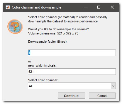
Whenever 3D volume rendering is selected, the current image volume is transferred into the 3D viewer. During the transfer, it is possible select color channels or to downsample the dataset to improve rendering performance:
collapse all
Composition of the 3D viewer
The 3D viewer has 2 main window:
-
3D Controls, the main window that is allowing to set parameters of the volume viewer, generate surfaces, make snapshots and animations. Most of controls are grouped under corresponding tabs in the window.
-
3D Viewer, the visualization window used to render volumes and models
User interface of the 3D viewer
Please refer to the corresponding sections for details.
collapse all
3D Controls -> Menu
Expand to see details of the menu entries
Menu gives access to the following operations:
| File section | |
| Load animation path | animations that are created using the 3D viewer can be saved and loaded back using this operation |
| Save animation path | save the current animation path to the disk |
| Make snapshot | starts the MIB snapshot tool to create an image snapshot of the current view shown in the 3D Viewer window |
| Make spin movie | starts the MIB movie maker tool to create a movie of a camera spin around the object displayed in the 3D Viewer window |
| Make animation movie | starts the MIB movie maker tool to create an animation movie, when the camera is following a predefined path. The path can be set using the *Animation tab* explained below |
| View section | |
| Default view | press to reset the view in the scene to its default state. The same can be achieved by pressing the Home button in the upper-right corner of the 3D Viewer window |
| XY view | press to set the view in the scene from above. The same can be achieved by pressing the Z button in the axes in the lower-left corner of the 3D Viewer window |
| XZ view | press to set the view in the scene from the Y-side. The same can be achieved by pressing the Y button in the axes in the lower-left corner of the 3D Viewer window |
| YZ view | press to set the view in the scene from the X-side. The same can be achieved by pressing the X button in the axes in the lower-left corner of the 3D Viewer window |
| Settings section | |
| Background color | press to set the background color for the scene rendered in the 3D Viewer window |
| Background gradient color | press to set the secondary background color to generate a gradient of background colors |
| Background gradient | enable to render background as a gradient of two colors selected using the menu items described above |
collapse all
3D Controls -> Viewer
Expand to see details of the Viewer tab
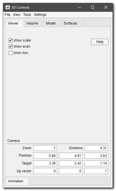 |
The Viewer tab is allowing to control the following widgets and parameters of the viewer:
- [✓] show scale use to show or hide scale bar that is shown in the 3D viewer window
- [✓] show axes use to show or hide 3D axes in the 3D viewer window. Click on the axes changes orientation of the 3D viewer
- [✓] show box use to show or hide bounding box drawn around the volume in the 3D viewer window
- Help press to open this help section of MIB
Camera
use these widgets to specify position of the camera; these values are interactively updated upon interaction with the 3D viewer
- Zoom camera zoom level
- Distance distance from camera to the center of the scene
- Position camera position or viewpoint as a 3-element vector of the form [x y z]. The camera is oriented along the view axis, which is a straight line that connects the camera position and the camera target. Changing the CameraPosition property changes the point from which you view the volume. For an illustration, see Camera Graphics Terminology
- Target camera target as a 3-element vector of the form [x y z]. The camera is oriented along the view axis, which is a straight line that connects the camera position and the camera target.
- Up vector upwards direction for the camera as a 3-element vector of the form [x y z]. By default, the z-axis is the up direction ([0 0 1]).
|
collapse all
3D Controls -> Volume
The Volume tab contains tools for interaction with the shown volume.
Expand to see details of the Volume tab
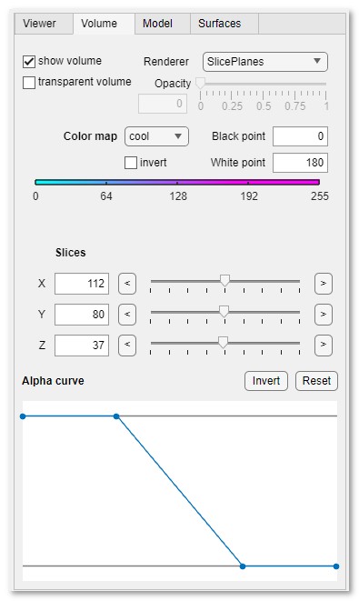 |
List of widgets for tweaking the visualization settings for the loaded volume:
- [✓] show volume, toggle whether both the volume and the model are shown or hidden. This checkbox does not affect visualization of surfaces
- [✓] transparent volume, toggle visualization of the volume. This checkbox does not affect visualization of models and surfaces
- Renderer ▼
- VolumeRendering, render the volume using volume rendering technique based on the specified color and transparency for each voxel
- GradientOpacity, render the volume based on the specified color and transparency with an additional transparency applied if the voxel is similar in intensity (grayscale volumes) or luminance (RGB volumes) to the previous voxel along the viewing ray. When a volume with uniform intensity is rendered using "GradientOpacity", the internal portion of the volume appears more transparent than the "VolumeRendering" rendering style, enabling better visualization of the intensity or luminance gradients in the volume. Use the Opacity slider to fine-tune the visualization
- SlicePlanes, use orthogonal slice planes for visualization. The slices can be changed using the Slices sliders or interactively using mouse
- Isosurface, show an isosurface of the volume specified by the value in the iso-value slider
- MaximumIntensityProjection, render the voxel with the highest intensity value for each ray projected through the data. For RGB volumes, the luminance of the voxel in CIE 1976 L*a*b* color space
- MinimumIntensityProjection, render the voxel with the lowest intensity value for each ray projected through the data. For RGB volumes, the luminance of the voxel in CIE 1976 L*a*b* color space
- Opacity / iso-value, use the slider to tweak settings of the GradientOpacity and Isosurface modes
- Color map▼, use this dropdown to update the colormap for visualization of the volume. The [✓] Invert checkbox can be used to invert the color map and Black point and White point to set intensities for contrast adjustment
- Slices [only for SlicePlanes ▼], contains sliders to change positions of the orthogonal slices
- Alpha curve allows to define transparency for the volume.
Intensities matching the alpha curve values of 1 are opaque, while
intensities, where the alpha curve values are 0 are transparent.
The points can be modified using mouse clicks:
- Right mouse click select the point
- Left mouse click change position of the selected point
- ⇧ Shift + left mouse click add a point at the clicked position
- ^ Ctrl + left mouse click remove the closest point
The alpha curve can be inverted (Invert) or
reset to the default state (Reset)
|
collapse all
3D Controls -> Model
The Model tab contains tools for visualization of the model loaded into MIB.
Expand details of the Model tab
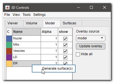 |
List of widgets for tweaking the visualization settings for the model overlay:
- Update overlay, press the button to grab layer specified in Overlay source ▼ and visualize it in the 3D Viewer
- Overlay source ▼ specify type of the layer for visualization as a model
- [✓] Hide all, toggle show/hide all selected in the table materials of the model
- Table with materials, the table contains the list of materials of the model. Each material can be shown/hidden and visualized using own transparency value (Alpha from 0 to 1). The right mouse click opens a dropdown menu, where the Generate surface(s) ▼ option can be used to generate surfaces that are shown using the Surfaces tab
|
collapse all
3D Controls -> Surfaces
Surfaces that are generated using a right mouse click over the table with materials in the Model tab are visualized using settings specified in this tab.
Expand to see details of the Surfaces tab
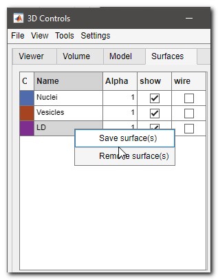 |
List of widgets for tweaking the visualization settings for surfaces:
- Table
- C, click to set color for the selected surface
- Name, double click to change name of the surface
- Alpha, tweak transparency for the selected surface (0-1)
- [✓] show, toggle show/hide the selected surface
- [✓] wire, toggle show/hide visualization of the selected surface as a wired model
- Additional settings via right mouse click ▼:
- Save surface(s), export the selected surface(s) to a file in SLT format
- Remove surface(s), remove the selected surface from the 3D viewer
|
collapse all
3D Controls -> Animation
The Animation tab allows to set key frames for making movies with volume animations. The rendering of animations is done using Menu->File->Make animation movie
Animations can be saved and loaded back from Menu->File->Load animation path and Menu->File->Save animation path
Expand to see details of the Animation tab
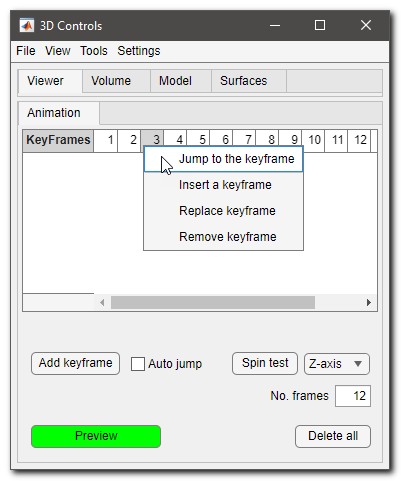 |
List of widgets for designing of animations:
- Keyframes table, animations are based on a set of key frames
that are added using Add. Upon right mouse
click a menu with additional operations is displayed:
- Jump to the keyframe, click to jump to the selected keyframe and update the viewer to visualize it
- Insert a keyframe, insert the currently shown scene into the keyframe sequence
- Replace keyframe, replace the selected keyframe with the current view
- Remove keyframe, remove the selected keyframe from the sequence
- Add keyframe, press to add a keyframe to the sequence of keyframes
- [✓] Auto jump, when checked a press over a keyframe automatically updates the scene in the 3D viewer to match the one stored in the keyframe
- Preview, press to preview the animation
- Spin test, press to test spinning of the volume around specified axis: Z-axis ▼
- No. frames, define number of frames for the preview
- Delete all, delete all keyframes
|
Back to Index --> User Guide --> Menu --> File
 https://youtu.be/840o6zni3KE


